
Airframe
Airframe is the skeleton of the drone: the frame you choose or draw, its arms, the hardware that holds it together, the straps and pad under the pack, and whether everything you bolt to it fits.
Where it is
Section titled “Where it is”Click Airframe in the section row. The section list shows five rows: Frame, Arms, Screws & standoffs, Layout & fit and Straps & pads.
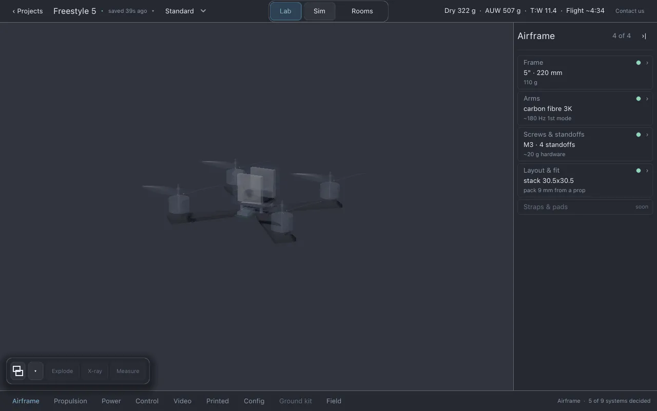
- Line 2: the frame’s size class and wheelbase (motor to motor across the diagonal), for
example
5" · 220 mm. - Line 3: the frame mass that flies. For an unedited catalog frame this is the vendor’s
weighed figure. Once you edit the frame in the designer, it becomes an estimate and carries a
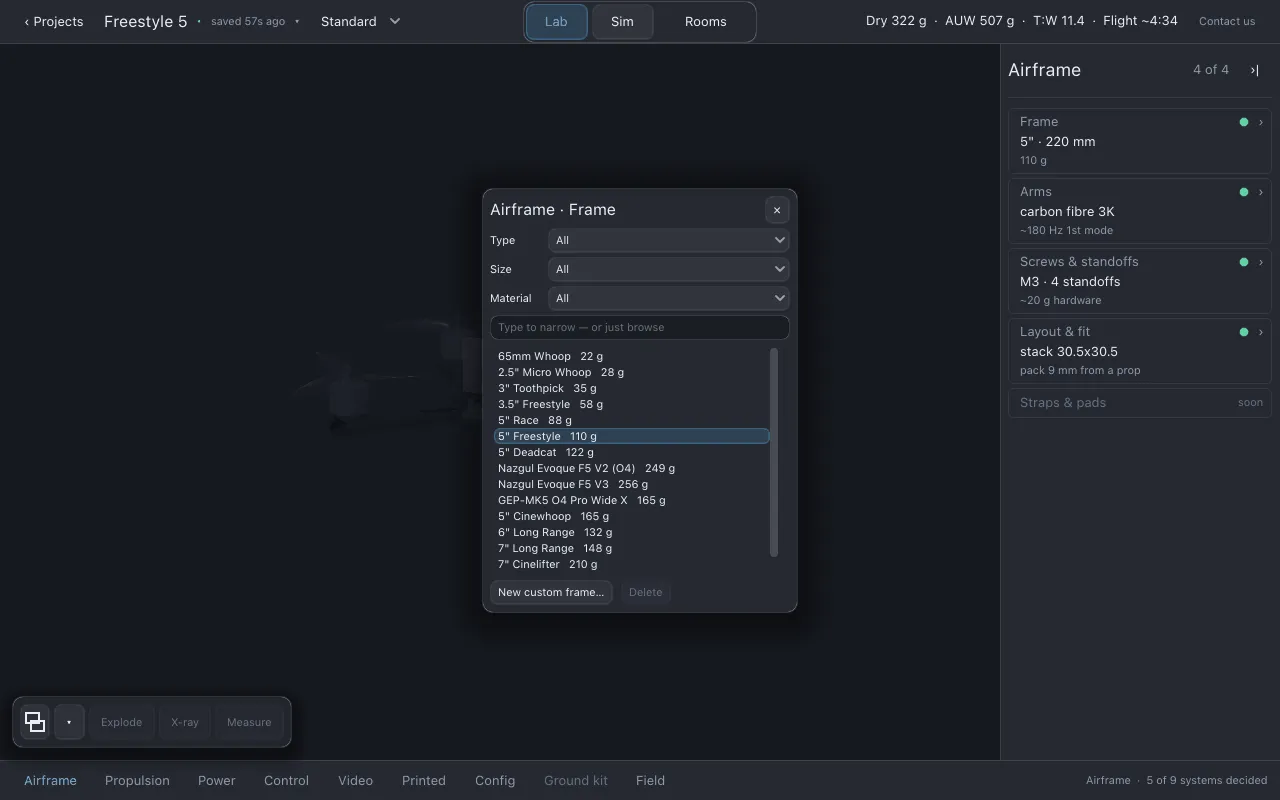
~. - Choosing a frame: click line 2 to open the part finder on the frame catalog.
- The page is the frame designer, described below.
A frame from the catalog also has its published figures (built around, material, frame mass, arm length, largest prop, motor mount) on its sheet, so the computed figures have something to be compared with.
- Line 2: the arm material.
- Line 3: the arms’ first bending mode with the motors fitted, for example
~180 Hz 1st mode. It carries a~because the model behind it is scaled from a guessed reference (see Guessed, sourced and measured). - The page draws the arms in plan beside the Arms sheet: arm length, section at the root, taper, the stock it is cut from, mass per arm and for all arms, tip stiffness, bending stiffness, bare first mode, root stress per newton, twist per newton-metre, and a strength ranking against the catalog’s plate frames. The two page numbers are the loaded first mode and the arm stock thickness.
There is nothing to pick here. Arms are cut from the same sheet as the frame, so you change them in the frame designer.
Screws & standoffs
Section titled “Screws & standoffs”- Line 2: the hardware the frame needs, for example
M3 · 4 standoffs. - Line 3: the hardware mass, for example
~20 g hardware. It is computed from the geometry, so it is an estimate of a typical hardware bag, not of the one you own. - The page shows the Fasteners sheet: standoffs, screws, hardware mass and its share of the frame mass, stack height, top plate height, motor screw engagement, and the assembly checks.
Layout & fit
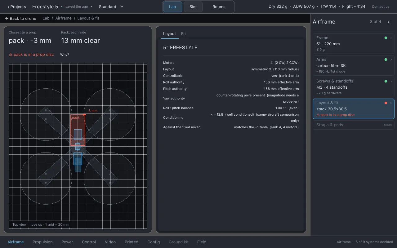
Section titled “Layout & fit”- Line 2: the stack mount pattern, for example
stack 30.5x30.5. - Line 3: the part closest to a propeller disc, for example
pack 9 mm from a prop. - The page draws the layout in plan beside two sheets:
-
Fit: mounts, shims and standoffs. These change the fit, not the flight numbers. There is a Pack mount choice (which plate the pack straps to) and sliders for prop spacer, motor soft mount, stack standoffs, pack fore/aft, prop imbalance, GPS mast height and camera uptilt. Each slider shows its value in millimetres (or grams, or degrees) and its range comes from the parts you have fitted. Reset to as-built puts them back. The pack’s overhang fore/aft and each side, and its clearance to the props, are measured here.
Shims and standoffs change only the geometry: what clears what. Where the pack is mounted and how far fore or aft it sits also move the centre of mass and the inertia. These settings are stored once for your Lothal install (
assembly_tweaks.json), not per drone. -
Layout: where the motors are and what that geometry alone decides: whether the layout can be controlled, roll, pitch and yaw authority, and how it compares with a standard quad mixer.
-
Straps & pads
Section titled “Straps & pads”-
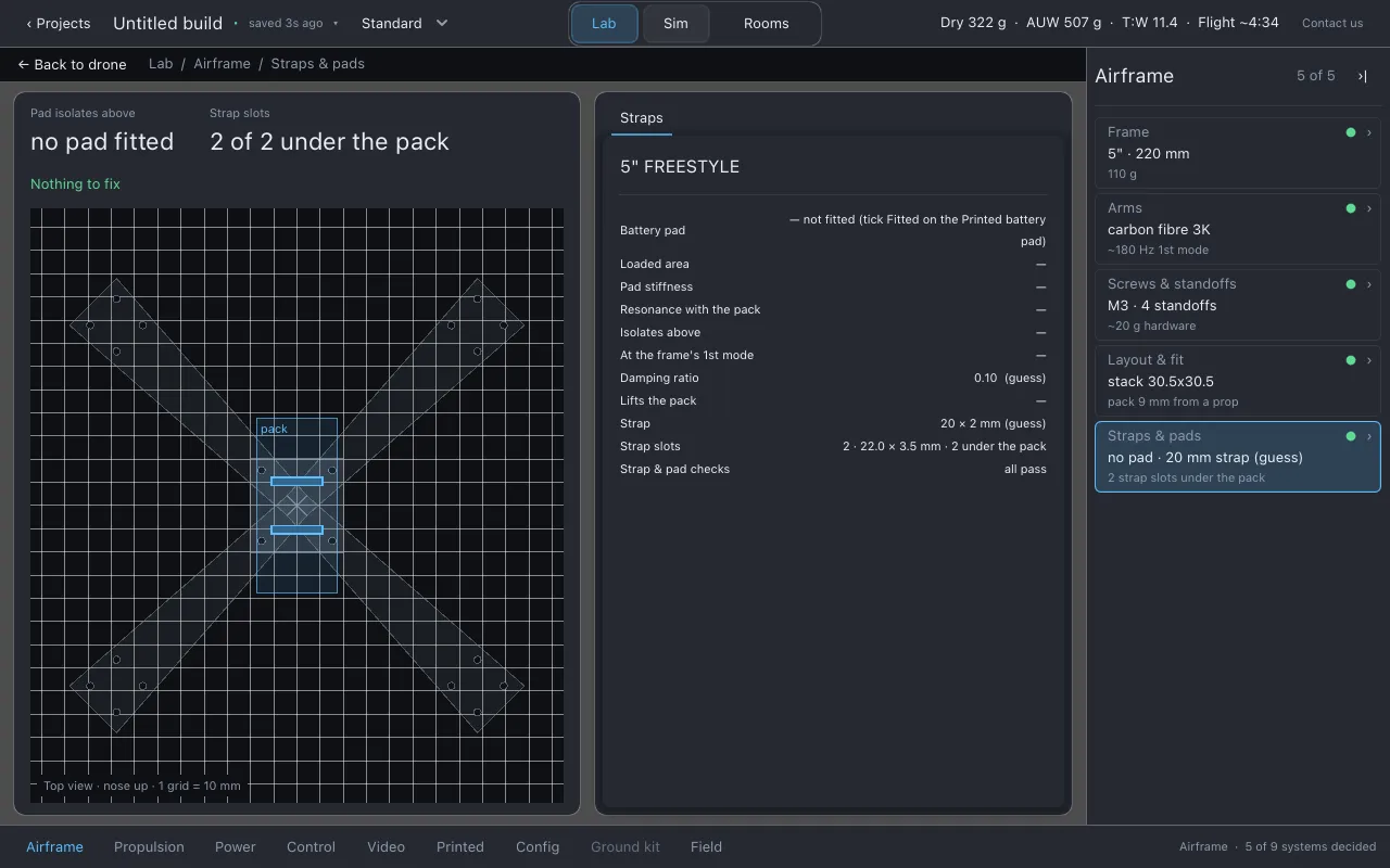
Line 2: the pad and the strap that hold the pack, for example
TPU pad 2 mm · 20 mm strap (guess), orno pad · 20 mm strap (guess)on a build with no printed pad fitted. -
Line 3: where the pad starts isolating, as
~N Hz pad isolation corner. With no pad fitted, this reads the slot count instead, for example2 strap slots under the pack. -
The page draws the seat plate’s slots against the pack’s footprint beside the Straps sheet, which has these rows:
- Battery pad: the pad’s material, thickness and plan size when a printed pad is fitted; not fitted otherwise, with a pointer to the Fitted tick on Printed → Battery pad.
- Loaded area: the pack’s footprint minus the two slot openings, with the pack’s mass beside it.
- Pad stiffness: the pad’s spring, in meganewtons per metre. A ranking figure, not a measurement.
- Resonance with the pack: the natural frequency of the pack sitting on the pad, in hertz.
- Isolates above: the frequency above which the pad lets through less than it would without any pad, in hertz. Below this a pad amplifies rather than isolates.
- At the frame’s 1st mode: how much of the frame’s ring the pad passes to the pack at the frame’s loaded first mode, with the verdict isolates or passes it through.
- Damping ratio: labelled (guess).
- Lifts the pack: how far the pad raises the pack above the plate, and the pad’s own mass.
- Strap: the strap’s width and thickness, labelled (guess) when they are the defaults rather than something you set on Printed → Battery pad.
- Strap slots: how many slots are cut in the seat plate, each one’s size, and how many sit under the pack.
- Strap & pad checks: all pass, or the number flagged and the most serious one.
The two page numbers are Pad isolates above (the pad’s corner frequency and the frame’s own ring, side by side) and Strap slots.
The frame designer
Section titled “The frame designer”Clicking the Frame row opens the frame designer on the stage. It has four areas:
- Left, the shelf. Nine layouts to start from, drawn as diagrams with each motor’s rotation: Quad X, Quad I, Hex I, Hex V, Hex Y, Hex IY, Oct X, Oct I and Oct V. Below them, the frames you have saved.
- Centre, the canvas. 2D is the plan you draw in. 3D shows the same frame extruded: click a plate to select it, drag it to move it, and drag empty space to orbit.
- Right, the controls. Frame name; arm length, width at root and tip, arm stock and plate stock; centre plate; stack height; motor and stack bolt patterns; Alternate motor directions. With an arm selected: its angle, length, root and tip width, and Clockwise. Every dimension is a slider you can drag and a box you can type in.
- Below, the numbers. Drawn mass, CG offset, roll and yaw inertia, and the checks. Details ▾ opens the full structure, arms, fasteners and layout figures.
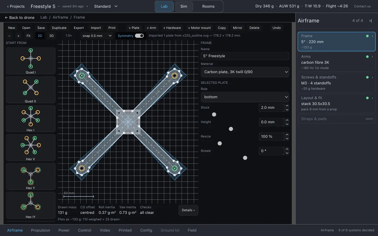
Toolbar
Section titled “Toolbar”| Button | Does |
|---|---|
| New, Open, Save, Duplicate | Start, open, save and copy frame documents. Saved frames appear on the shelf. |
| Export | Writes one of five files. See Exports. |
| Import | Brings in an outline from an SVG or DXF file as plates you can edit. See Importing frame outlines. |
| Opens the 1:1 print sheet in your viewer, ready to print at 100%. Print it and lay your parts on it to check the scale. | |
| + Plate, + Arm | Add a plate or an arm. |
| + Hardware | Adds an M3 standoff and its two screws on the selected plate. |
| + Motor mount | Cuts a motor’s four bolt holes into the selected plate. |
| + Stack mount (and its pattern picker) | Cuts the flight stack’s four bolt holes into the selected plate, on the pattern chosen beside the button. The picker lists 20×20 M2, 25.5×25.5 M2, 25.5×25.5 M3 and 30.5×30.5 M3; the thread is spelt out because a bare 25.5x25.5 is an M2 stack. The pattern is centred on the selected plate and the add is refused if it does not fit, with the plate unchanged and no undo step. |
| + Camera cage (and its camera picker) | Adds two upright side plates on the camera bay, spaced for the camera class chosen beside the button (Nano 14 mm, Micro 19 mm or Full 26 mm, the widths of the catalog’s three analog cameras). Each plate has an M2 pivot hole and a 0–50° tilt slot. No selection needed: the cage seats itself on the bottom plate’s front edge. |
| Copy | Copies the selected plate. |
| Mirror | Repeats the selected arm around the centre, once per arm the layout has. |
| Delete | Deletes the selected plate, and the motor standing on it if it is an arm. |
| Undo | Steps back one edit. |
| −, +, Fit | Zoom out, zoom in, and frame the whole drawing. |
| 2D, 3D | Switch the canvas view. In 3D, upright side plates stand on their base and flat plates lie, so a cage reads as a cage. |
| snap | Snap step: 0.5 mm, 1 mm, 5 mm or off. Hold Ctrl while dragging to ignore it. |
| Symmetry | When on, dragging a corner of one arm moves the matching corner on every arm. |
Keys on the canvas: F fits the drawing to the view, S turns symmetry on and off, and Ctrl+Z (Cmd+Z on macOS) undoes.
What reaches the drone
Section titled “What reaches the drone”The designer edits the frame that is fitted. An unedited catalog frame flies with its
published mass and arm length. When you edit it, the frame that flies changes by what your edit
changed, in mass and in arm length, and those figures then carry a ~. Plate thickness and
standoff heights drawn in the designer do not move where parts sit on the drone in this
version.
Sim flies quads only. If the drawn frame does not have four motors, it is not flown, and the
Frame row says drawn frame not flown: not a quad.
Exports
Section titled “Exports”| Export | Use it for |
|---|---|
| Print sheet (SVG, 1:1) | Printing on paper at 100% to check sizes against real parts. |
| Cut sheet (SVG, nested) | The plates laid out for cutting. |
| Cut file (DXF) | Sending to a CNC or laser-cutting service. |
| Assembly (STL) | Opening the assembled frame in another 3D program. |
| Build sheet (HTML: parts, hardware, cost) | A printable page listing every plate (role, thickness, material, size and quantity), every screw by length and every standoff, strap and pad sections when they are there, a camera cage section when there is one, an assembly order and a cutting cost range from placeholder rates. |
Below the five exports, the menu has three more entries:
- Cutting bit: 1/16” (1.59 mm, the typical shop value), 1/8” (3.18 mm) or 1/32” (0.79 mm). The ready-to-cut check and the export notes assume the bit chosen here.
- Round inside corners to the bit: fills every inside corner tighter than the bit’s radius, on every plate, with the fillet the router would leave anyway. It is one undo step.
- Countersink selected plate’s screw holes (toggle): marks the selected plate’s round screw
holes as countersunk. On the DXF they move from the plate’s
<ROLE>_HOLESlayer to<ROLE>_COUNTERSINK. The SVG draws a dashed blue ring over each one at 1:1.
Exports are written to the exports folder and Lothal opens it. See
Exports.
What to watch for
Section titled “What to watch for”Warnings on this section’s rows include (short forms as the rows show them):
- Frame:
frame has no plates,frame has no arms,frame has no motors,motor layout cannot be controlled,drawn frame not flown: not a quad,custom frame — unchecked,frame mass outside catalog range. - Arms:
an arm has no centreline,an arm centreline leaves its plate,arm section outside catalog range, and notes when the frame rings near where the drone hovers. - Screws & standoffs:
a screw bottoms out,too little thread engaged,hole too close to the edge. - Layout & fit:
a part is in a prop disc,pack is in a prop disc,pack is wider than the plate,a part is larger than the plate,two parts overlap,a part overhangs its mount,mount pattern does not match,a part has nothing to mount to.
Warnings never stop you. See Fit checks and warnings.
Honest limits
Section titled “Honest limits”- The arm’s first mode is scaled from a reference frequency that has not been measured. Treat it as a ranking between frames, not a number to trust on its own.
- The drawn frame models plates and arms. A real frame’s side plates, camera plate and small details are not all drawn, so its drawn mass can differ from the weighed one.
- Straps and pads are not modelled.
- An imported outline has limits; see Importing frame outlines.
Related
Section titled “Related”- Frame bench: test how the frame’s inertia changes how fast the drone rolls.
- Physics is the source of truth
- Parts catalog
Documentation licensed underCC BY 4.0. Lothal itself is GPL-3.0-or-later.Report a problem.Roadmap.